PCB Design for ESP32 Stand alone module
-
@Sharon-Sebastian Thanks for the reply. But as I am still in the prototyping stage there is obviously a great need for me to program my MCU frequently to validate it's working.
- 9 days later
-
@salmanfaris
i tried uploading a code to the Esp32 by connecting to arduino with the connection below
Arduino Tx to ESP32 Tx0Arduino Rx to ESP32 Rx0
Arduino 3v3 to ESP32 3v3
Gnd to Gnd
And connecting Arduino Reset Pin to ground....
I could read the esp32 from the serial monitor but the code is not getting uploaded to the board(esp32).. I am trying this method so that if it works i wont have to add Jtag or USBtoUART on my pcb..
Thanks.. - 8 months later
-
@kowshik1729 Hey did you eventually get the PCB design for this finalized?
-
@mgfuller333 No not yet, but there seems a quite nice progress in the design. I'm still researching on the antenna interfacing part.
- about a month later
-
Hi All, i m also facing the same error. we are developing an iot device based on esp32d0wdq6 controller. we have designed a board. Now the program is not getting uploaded. the connections are
TTL Converter 3.3v - vcc (ESP32)
TTL Converter gnd - gnd (ESP32)
TTL Converter TXD - RXD (ESP32)
TTL Converter RXD - TXD (ESP32)
GND - GPIO 0 (ESP32)
3.3V - EN (ESP32).
Connecting......................................____An error occurred while uploading the sketch
_
this is error message i m getting.A fatal error occurred: Failed to connect to ESP32: Timed out waiting for packet header
FYI, we are using the W25Q40CL flash ic. please help me to sort out this issue.
Thanks in Advance ! -
And having one more doubt !
Bootloader for esp32 will present already or we need to load the bootloader code into the newly brought esp32 chip ? -
@Sharmila If you're programming the board for the first time using Arduino IDE then you need to burn the bootloader into the bare IC. I have a doubt when you said the IC is not getting programmed even though the GPIO0 is low.
I wanna know is GPIO0 low all the time or did you pull it low momentarily using a button??
-
@kowshik1729 Yes i m programming the board first time using arduion. GPIO 0 is low all the time.
-
@Sharmila GPIO0 must not be low all the time. It must be held low only for a moment. Because GPIO0 is a boot strap option for choosing between UART download and normal operation. Please refer to the datasheet and search boot strap. And also can you please post a snap of your newly designed board please?
-
@kowshik1729 thank you for the hint ! i will check it . schematic picture of my board is given below
(
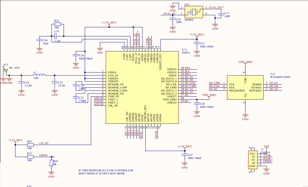 )
)
Recent Posts
-

Hi all,
I recently came across this post where they have shown photos printed on PCB in high resolution. I would like to know how to add this kind of photos to the silkscreen layers of the PCB in Eagle/Altium.
Adding such kind of photos will be attractive for beginners and also can be used for educational purposes too.
Please let me know in case anybody knows. -

@kowshik1729 I think that might not get since the platform is not opensource! but they provided everything you need to develop a system with that.
-

@kowshik1729 Carrier board schematics for SoMs will be always available as they need to be modified as per customer application, however SoM design files are hard to get unless the H/W design is truly open-source.
-
@salmanfaris Actually the schematics files you've mentioned are the same files which I've got from them. They are carrier board design files.
